Home .
Testing Capabilities .
Research .
Downloads .
Contacts .
Links
Voided Shaft Construction
Task 3: Attenuating Mass Concrete Effects in Drilled Shafts (BD-544-39)
WebCast
Voided Shaft Construction WebCam
Overview
This task involves casting a 9 ft diameter shaft with a full length 4 ft diameter central void essentially forming a cast-in-place cylinder pile. The purpose of this effort is to demonstrate the construct-ability and measure the temperature generation throughout the entire shaft.
Background
The genesis of the voided shaft concept stems from excessive temperature levels that develop in large diameter shafts which often exceed both differential and preferred maximum temperatures. As the central most concrete is least advantageous from a strength and durability standpoint, its absence has little to no adverse effects. Even though it reduces the amount of required concrete, it adds complexity to the construction.
Numerical modeling of large diameter shafts show that shafts greater than 5 ft in diameter all have the potential to store heat energy without means of dissipation through a 2.5 ft thick (or greater) rind around the core. Therein, larger diameter shafts have larger cores all of which are subject to this intense heat.
Field Preparation
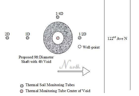
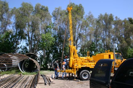
Surrounding Soil: In preparation for this task, the soil around the proposed excavation location was instrumented with 2 inch diameter SCH80 access tubes at various distances from the edge of shaft. Each access tube extends 30 ft into the ground. These ground monitoring tubes (4 total) and a wellpoint were installed by FDOT District I drill crew. The spacing of the monitoring tubes were positioned at 1/4, 1/2, 1, and 2 diameters from proposed edge of shaft. Thermocouples were placed on the ground monitoring tubes located at the proposed midpoint of the shaft (12.5 ft depth).
 Proposed layout of the test site.
 Installation of ground monitoring tubes by FDOT District I.
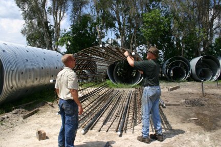
Reinforcing Cage: The reinforcement cage was built using 36 longitudinal bars and 26 - #5 stirrups with a spacing of 12 inches on center. The reinforcement cage was equipped with 9 - 26ft long, 2 inch Schedule 80 PVC pipes for thermal testing and cross-hole logging. Thermocouples were placed on three of the monitoring tubes (120 degree separation) at the top, middle, and bottom of the tubes.
 Reinforcement cage with monitoring tubes and thermocouples.
The central casing is slightly smaller than the targeted 48 inch with a 46 inch outer diameter and a ½ inch wall thickness; it is 30.5 ft long.
Construction Site and Schedule
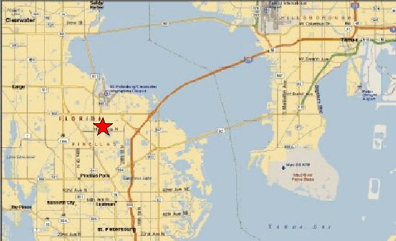
The test site is located at R.W. Harris, Inc., 12300 44th St. N. in Clearwater, FL.

Construction is scheduled for Tuesday, September 25th, from 8 am to 12 pm.
Contact Us
If you have questions or comments regarding Attenuating Mass Concrete, please contact Gray Mullins at gmullins@eng.usf.edu.

 Proposed layout of the test site.
 Installation of ground monitoring tubes by FDOT District I.
 Reinforcement cage with monitoring tubes and thermocouples.
