CFRP Bridge Test Video Stream, northeast view (Oct 2020)
CFRP Bridge Test Video Stream, southwest view (Oct 2020)
 50% Steel Loss Video (1999-2001) 50% Steel Loss Video (1999-2001)
|  All Test Results All Test Results
Project Overview
Corrosion is a quiet killer of marine structures in Florida wherein the full effects are often hidden or unknown. In the late 1990s, the first of 12 research projects was undertaken dealing with the loss in axial load carrying capacity caused by corrosion. This was followed closely thereafter looking at the loss of lateral load carrying capacity of typical bent type bridge piers. Later, innovative repair schemes using fiber reinforced polymers applied underwater were evaluated. Therein, multiple epoxy or urethane based adhesive systems were used to bond glass or carbon fiber fabrics to the piles. Repairs were held in place using shrink wrap, vacuum bagging, or pressure bag application techniques while the resins cured. These repairs were shown to reduce corrosion rates while also providing strength restoration.
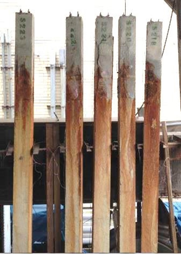
Twenty-one years later, five remaining piles originally cast in 1999 for the lateral capacity study have been carefully evaluated to document the present corroded condition. No reinforcing steel remained intact in the simulated splash zone and the cover was badly spalled. The cover, if not already fallen off, was removed, the core concrete surface was cleaned, the section was formed and poured back to the original dimensions, and two layers of uniaxial carbon fiber were bonded to the affected region forming an exoskeleton to replace the lost steel reinforcement.
The test bridge bent was built to exactly match the five bents tested between 1999 and 2001 which included a control bridge with no steel loss and progressively more steel loss up to 50% (0, 10, 30 and 50% loss). It is the intent to show full capacity restoration which could be applicable to aging bridges in the FDOT inventory.
Background
Pilot Study (1999-2002)
In the pilot study, 4 one third scale bridge bents were tested at varying levels of corrosion; no corrosion, 10%, 30% and 50% steel loss. Each bent consisted of 5, 6in by 6in piles with 5/16in prestressed strands, a uniform concrete pile cap and fixed concrete footing. To simulate 50 years of corrosion, pile splash zones were cast using a cure accelerating admixture containing chloride contamination. This admixture made up 3%, by weight, of cementitious material within the assumed splash zones of each pile. These zones were meant to be representative of tidal zone corrosion experienced by bridges in Florida. After the desired corrosion level was achieved the piles were tested. Results from the experiments are shown in the figure below.
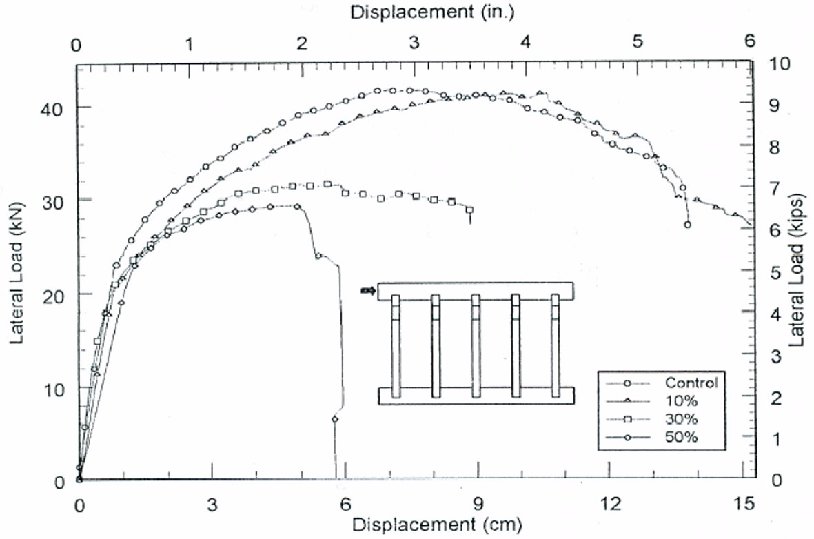
During testing, the piles corroded to 50% area loss of steel (ALOS) failed abruptly at a significantly lower lateral displacement than the other piles tested. This failure occurred in the corroded zone as expected. The results of the tests by percentages are summarized as follows; 10% reduction in steel area resulted in a 1% loss of capacity, 30% reduction in area resulted in 24% loss of capacity and 50% reduction in area resulted in a 30% loss of capacity. The figure below shows the catastrophic break which occurred during the test of piles corroded to 50% ALOS.

Modeled Repairs (2017)
This study implemented a non-linear finite element analysis of the corroded piles to analyze the prestress lost due to a reduction of steel reinforcement. Area loss of steel for each pile was assumed to be 90%. The purpose of the study was to model the experimental results of the first study and calibrate a model for the repair of 5 piles using FRP wrapping methods. The simulated lateral load and displacement data obtained from the repaired bent models compared to the undamaged bent models indicated that full lateral capacity would be regained using FRP repair. Model results were shown to replicate the measure pile bent response for both the control and damaged conditions.
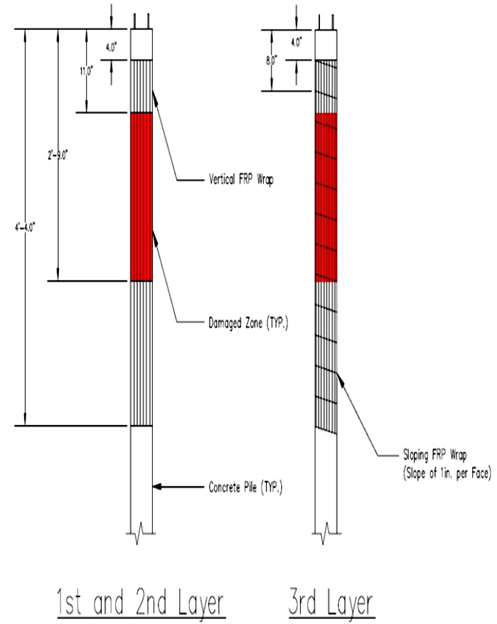
From the analysis it was also determined that 3 layers of FRP applied after initial concrete repair would supply adequate lateral support. Details of the wrapping pattern are provided in Figure 4; the first 2 layers provide bending resistance and the third layer provides passive confinement and shear resistance.
Current Study
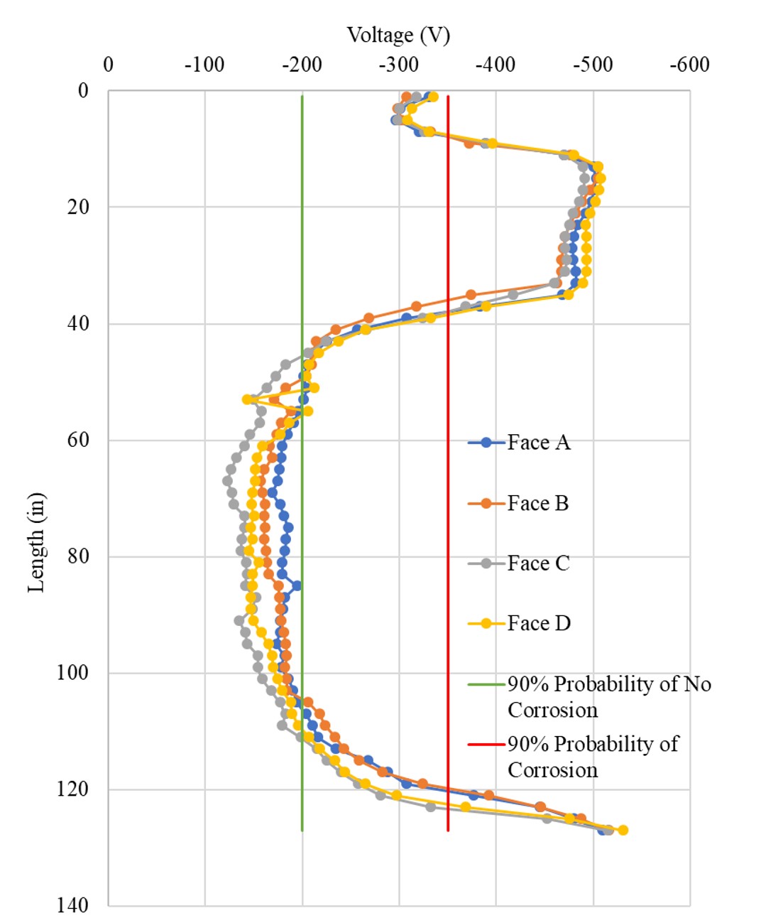
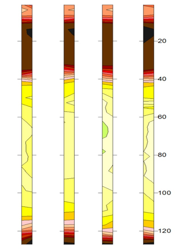
The piles used for this study are the last remaining piles from the pilot study and are the same piles used for the models developed in the second study. To determine the current corrosion levels in the piles and an adequate repair area, piles were analyzed using ASTM C876-09, Standard Method for Corrosion Potential of Uncoated Reinforcement Steel in Concrete. Results from this Electrochemical Impedance Spectroscopy (EIS) test were used to develop contour corrosion maps for each pile face as shown in the figures below. For each pile, 2-inch by 2-inch squares were marked along the 11-foot length of each pile on each face. Surface potential readings were taken at the center of each square using a CuCuSO4 electrode with a 2-inch diameter head and a voltmeter.
Based on the results of the corrosion analysis, the full repair length was determined to be 4 feet for each pile. The damaged concrete cover was removed from each pile over the repair length and the remaining sections were pressure-washed and ground to remove any compromised concrete. Sections were then reexamined to determine the amount of viable steel remaining. Based on the results of the EIS analysis, it was no surprise that there was no viable steel remaining in each section meaning each pile experienced 100% ALOS.
Pile Repair
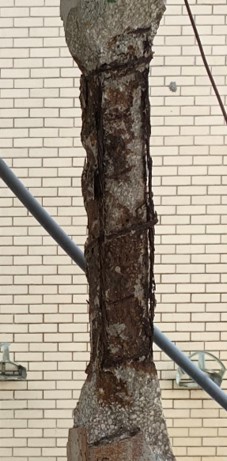
Each pile was soaked for 24 hours, then left to dry for 2-3 hours, to achieve saturated surface dry (SSD) conditions over the length of the repair area. Piles were repaired using a removable vertical steel form and a rapid setting concrete mortar. Twenty-four hours after repair, the form was removed and the pile was soaked for 72 hours. The pile repair scheme is showcased in the figure below.
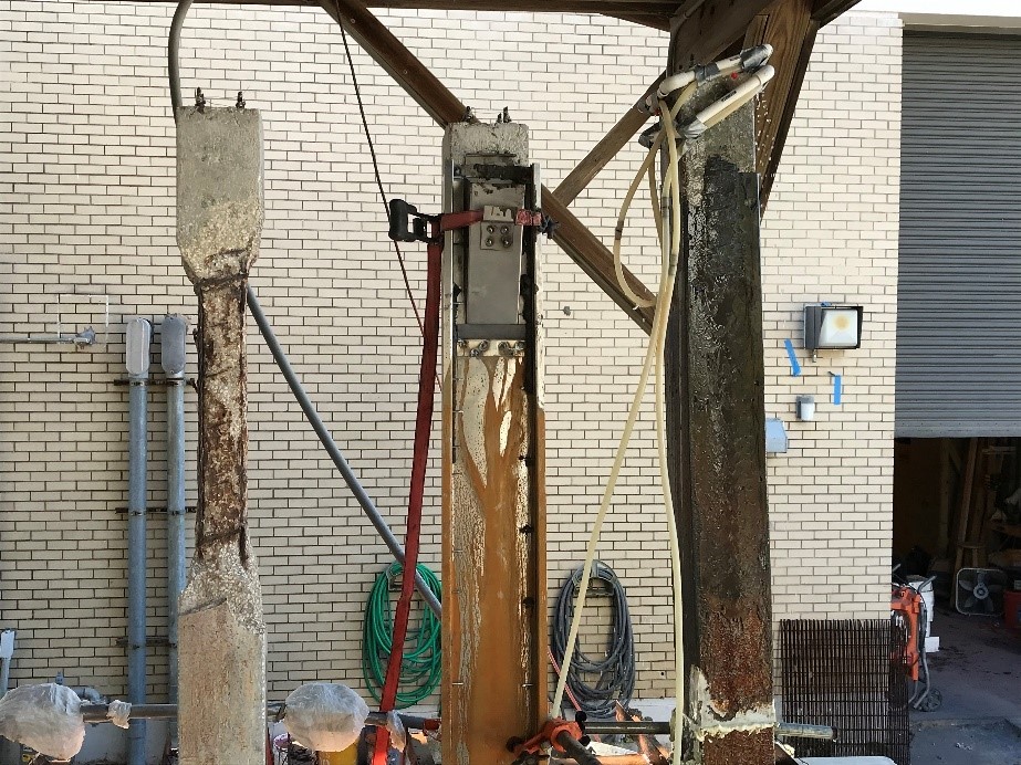
Shown below is the condition of the piles just prior to the application of CFRP wrap.

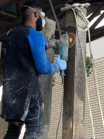
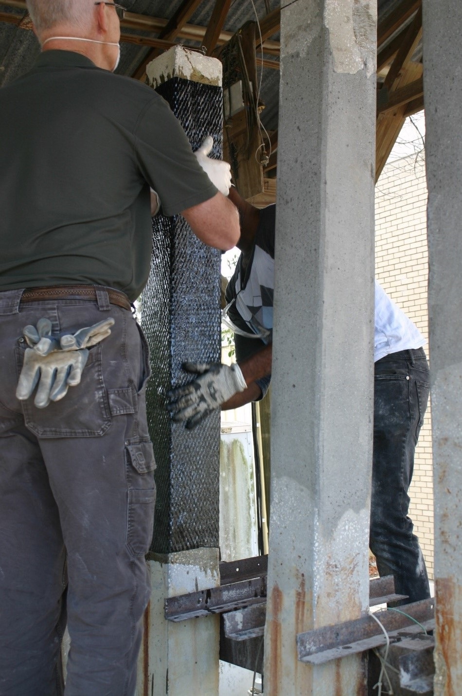
Uniaxial CFRP fabric, cut for longitudinal reinforcement, was impregnated with epoxy resin then applied to the pile. While the single longitudinal layer was being positioned, a 20ft long x 6in wide uniaxial CFRP confinement strip was saturated and applied by wrapping one full revolution around the pile then spiraling down the pile at a pitch of 1.5in down for every 6in side. The 6in spirals were aligned directly beside the previous without overlap. Finally, layers of stretch wrap plastic, bubble wrap, and stretch wrap were applied to consolidate the FRP. The bubble wrap was used to more uniformly apply pressure to the flat sides of the pile by converting the square section to a more rounded cross section.
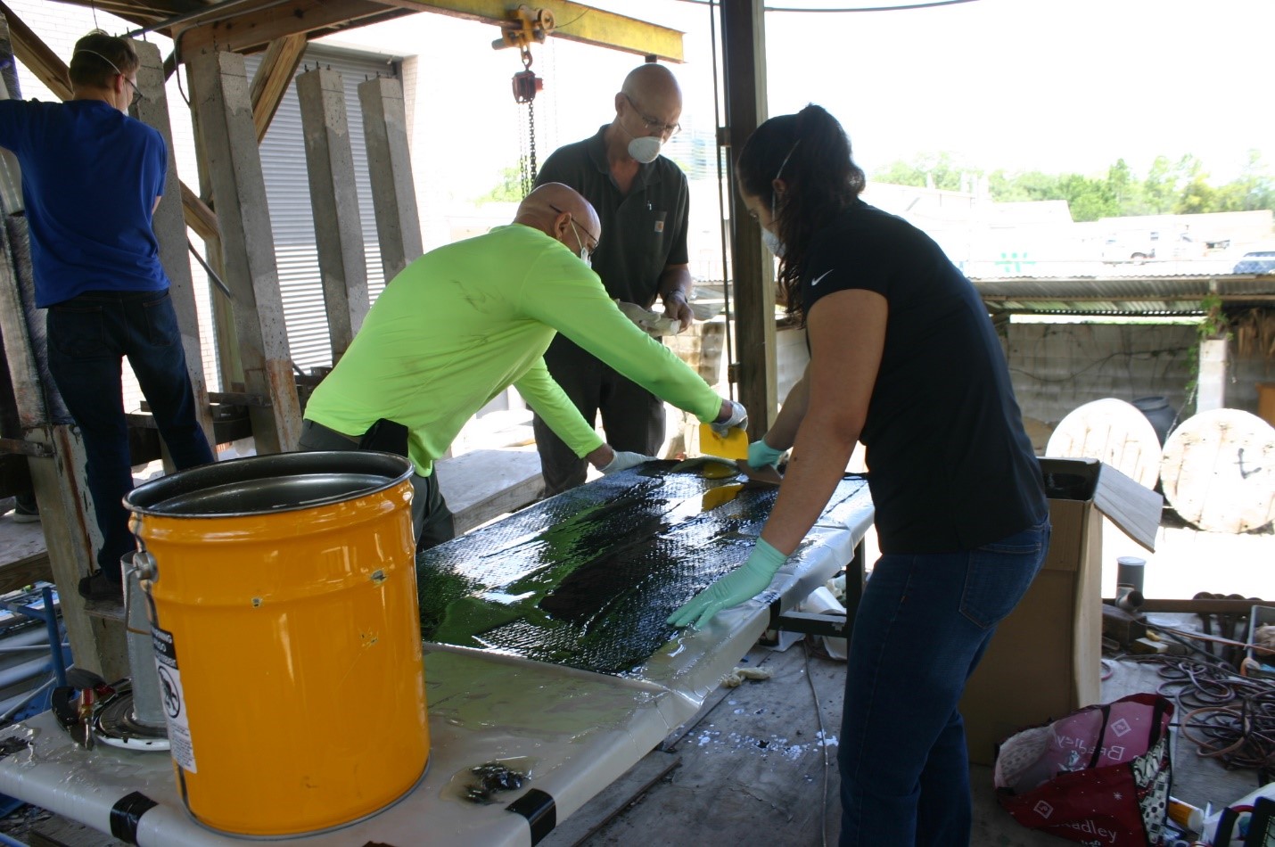


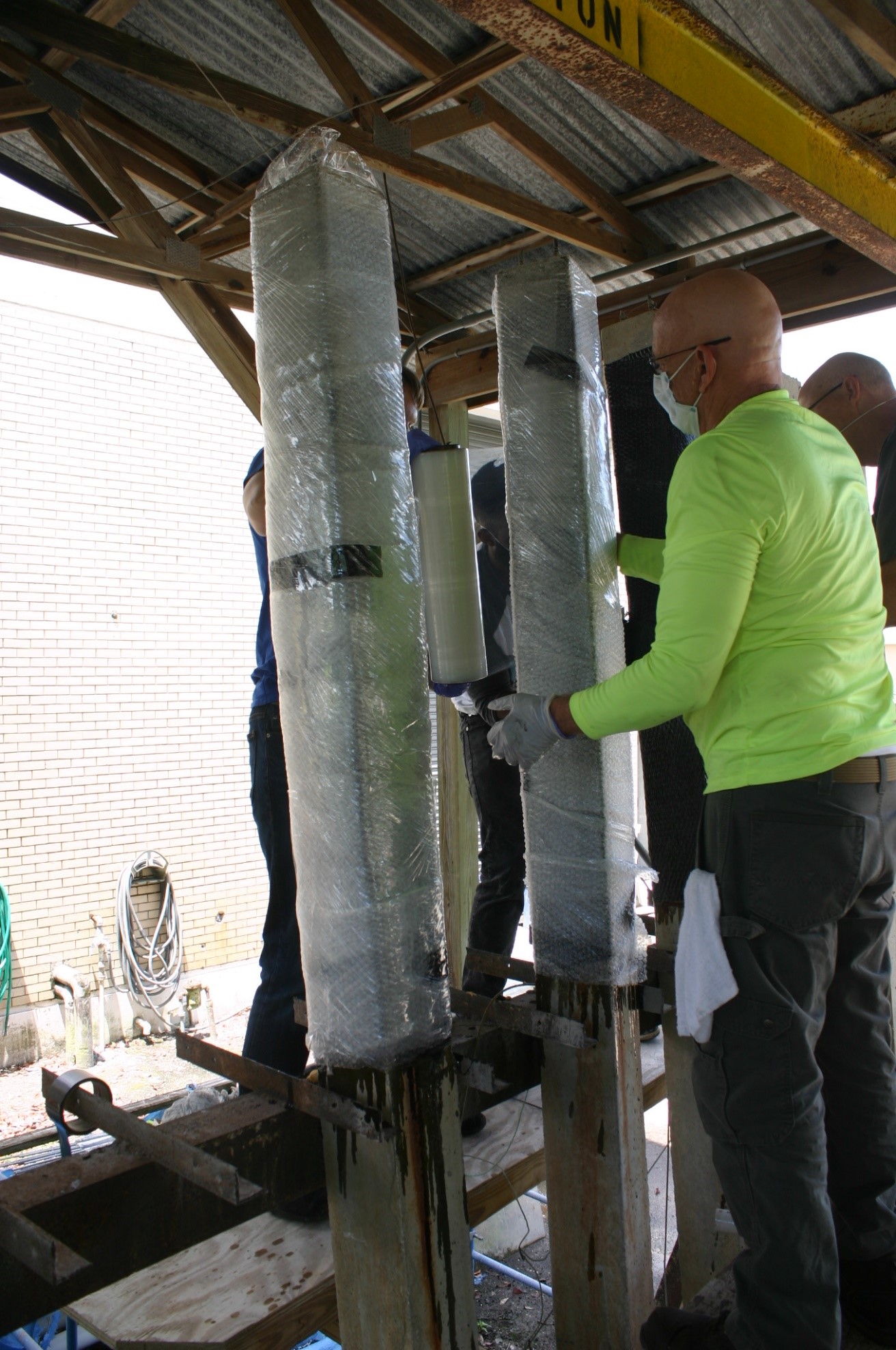
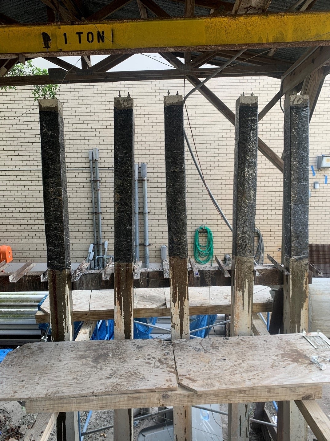
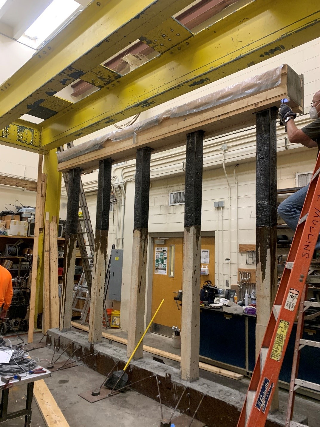
Repaired piles were then used to construct a one third scale model bent identical to that of the first study, Results from the test of this bent will be compared to those of the first study to determine the adequacy of CFRP repairs for regaining lost lateral capacity. CFRP is notably good for corrosion mitigation and this added benefit could further propel the use of this material in bridge maintenance. The completed bent is pictured in the figure below.
The Test
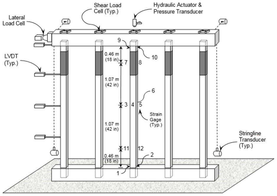
A lateral load will be applied to the cap of the bent using a hydraulic actuator. To simulate service loads, jacks above each pile will be loaded to 10 kips during the test while the effect of the loads will be confirmed using shear cells under each jack. Each pile is outfitted with strain gages at the top, middle and bottom of the pile, on each face to monitor the strain experienced at each location. Displacement transducers located at four positions along the first (trailing) pile monitor lateral displacement throughout the test while string line transducers monitor the position of the bent perpendicular the direction of the lateral load. All transducers and loading mechanisms are monitored using an Optim Megadac, the main data acquisition system for this test. An example of the test setup is shown below as well as the final set up in the lab.
Acknowledgements
All reapair materials were supplied by Sika Group, Coastal Construction Products and with the help of the local International Concrete Repair Institute (ICRI) chapter.
| 
 All Test Results